


Project Date:
May 25, 2016
Purpose
To measure the relative performance between direct-wired valves and valves controlled via a fieldbus in terms of timing. Fieldbus controlled valves have the potential to significantly reduce wiring and simplify installation. They also allow easy expandability in the field.
Method
For the purposes of this experiment, Festo magnetic sensors were placed on four Festo actuators and adjusted to signal when the actuator has reached the end of its stroke. These sensors were wired into four discrete inputs on the SLS remote I/O (1734-IB4). The sensors were placed on actuators 1B, 3A, 5B, and 7A. The SLS uses double ended actuators and the “A” or “B” designates which direction the actuator moves. For this experiment, two of each direction was chosen. Refer to Figure 1 below.
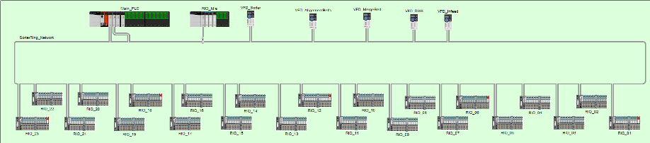
Figure 2 shows the network architecture of the SLS controller. The controller is Rockwell Automation ControlLogix based using Point I/O. Nineteen Point I/O nodes are placed on the network to replicate the real world network design for the Riverside, CA SLS. The magnetic sensors were wired into RIO_02 and control of the direct-wired valves was through RIO_01.
A simple program was written for the 1756-L72S controller that would record the amount of time between the output signal and the magnetic input signal. This timing was done using the WallClockTime variable within the ControlLogix processor which measures to the microsecond. A portion of the program is shown in Figure 3.
To validate the timing method used in this program, comparison data were taken using a 2-channel oscilloscope. Channel 1 of the scope was connected to the 24VDC output to one of the valves. Channel 2 was connected to the 24VDC input on the 1734-IB4 card that receives the signal from the magnetic sensor. By triggering the scope on Channel 1, the elapsed time could be very precisely measured between the output and input signals. Refer to the results section for validation data.
The first fieldbus device tested was an SMC Ex260-SEN1 unit. This device simply adapts the valve control to Ethernet/IP and is DLR (Device Level Ring) compatible. For the purposes of this test, only one leg of the DLR was connected. Figure 4 shows the Ex260 module connected and operating. Figures 5 through 10 show screenshots of how the Ex260 was configured in the I/O tree within the Studio 5000 project. Note that the 4ms RPI (Requested Packet Interval) is the minimum allowed by the module. Note also that the Ex260 can only operate in Multicast mode and does not support Unicast connections.
The second device tested was an SMC Ex600-SEN1. This device is very similar to the Ex260 but adds the capability of installing up to 31 modules of general purpose I/O (discrete or analog). Like the Ex260, only one half of the DLR was connected since the particular test module was not DLR capable. Figure 11 shows the Ex600 connected and operating. Figures 12 through 16 show screenshots of how the Ex600 module was configured in Studio 5000. Note that the 2ms RPI is the minimum allowed by the module. The Ex600 supports both Multicast and Unicast – for this test, Unicast was used.
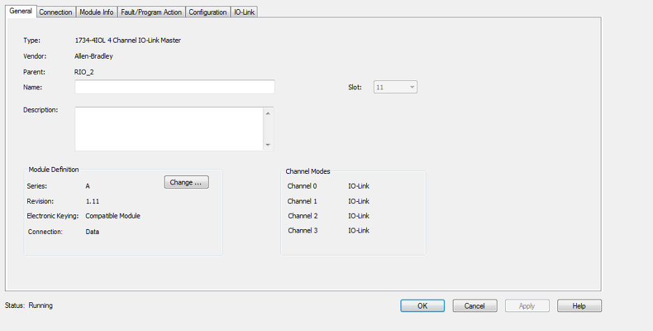
The final module tested was a Festo IO-Link VAEM-L1-S-16-PT. This module has the added benefit of only requiring a single 5-conductor connection that carries both power (24VDC) and all signals using IO-Link. The IO-Link master used as an Allen-Bradley 1734-4IOL which supports four IO-Link devices. For this test, only channel 0 was used and the others were not configured or used. Figure 17 shows a photo of the Festo module connected and operating. Figures 18 through 23 show screenshots of how the module is configured in Studio 5000.
Finally, a direct-wired Festo DB45 (VAEM-L1-S-M1-44) was tested as a comparison to the Festo IO-Link module and eliminate speed differences between SMC and Festo as a confounding factor. Figure 24 shows the direct-wired (DB45) manifold connected and operating.
Results
The results of the validation test using the 2-channel oscilloscope are shown in Table 1.
Although this table shows a fairly significant difference between the PLC timing test and the oscilloscope (average 5.93ms), the difference is relatively consistent. This difference is primarily caused by two main factors: network delays from the remote I/O modules to the PLC, and the scan time of the PLC. The RPI of the remote I/O modules was set at 2ms which is the fastest allowed by the 1734-AENTR module. This can lead to, at worst, a 4ms delay assuming the PLC is scanning infinitely fast. The typical scan time of this simple program was typically 0.8 to 1ms. Therefore, the worst case timing measurement would be PLC Scan + Output RPI + PLC Scan + Input RPI + PLC Scan which yields approximately 7ms. Based on this validation, it was determined to take 100 sequential samples for each setup to average out variability in the above process and regress toward the mean 5.93ms delay.
Based on the data in Table 1, all the numbers presented below need to be reduced by 5.93ms to reflect real world timing values. However, the primary purpose of this experiment was to compare the relative reaction time of different fieldbus modules so the 5.93ms delay is not important as it affects all the tests equally.
Table 2 shows comparison results of all the tests.
Conclusions
Analyzing the average delay time of all four valve/actuator combinations, it can be concluded that the SMC and Festo direct-wired manifolds and valves operate at almost precisely the same speed. This is to be expected as their mechanisms of operation are almost identical with only minor design differences.
The SMC Ex260 SI unit operates, on average, 0.65ms slower than the direct-wired equivalent. The SMC Ex600 SI unit operates, on average, 2.76ms slower. Finally, the Festo IO-Link module operates, on average, 12.33ms slower. From this data, it can be concluded that the SMC Ex260 and Ex600 are both fully useable fieldbus adapters in future Intralox equipment and will have little to no detrimental impact on current design equipment. However, if machines are implemented requiring higher-than-normal operation speeds, careful analysis should be performed to determine the feasibility of these units. Also to be concluded from this data is that the Festo IO-Link module will work adequately on slow equipment but not to be used above approximately 125 feet per minute (20ms per encoder pulse at 0.5 inches per pulse).